
< Previous | Contents | Next >
Annex 2-4 Guidance for repairs by welding for cast steel crank throws
1. Applications
(1) Where defects are discovered in the crank throws of cast steel crankshafts under manufacture (including full built-up crank webs: hereafter called, the crank throws), repairs by welding may be carried out in accordance with the following standards. However where the depth of the de- pression from which all defects have been removed is less than 0.05![]() (
(![]() is the web s thick- ness), it is recommended that no repairs by welding be carried out. In this case the finishing of the base part of the depression shall be such that the rounding there is over twice the depth of the depression, and the angle between it and surface is sufficiently rounded up.
is the web s thick- ness), it is recommended that no repairs by welding be carried out. In this case the finishing of the base part of the depression shall be such that the rounding there is over twice the depth of the depression, and the angle between it and surface is sufficiently rounded up.
(2) When the manufacturer desires to carry out repairs by welding, he shall apply in advance to the Surveyor for approval. In the case the Surveyor has found that such repairs by welding are not suitable or has perceived that there are too many places to be welded in such repairs, he will not approve the application, advising scrapping of the crank throw in question.
(3) When the manufacturer desires to carry out repairs by welding, he shall arrange in advance for the crank throw to be subjected to the preliminary tests stipulated in 7 below.
2. The scope and conditions permitting repairs
(1) The base part of the pin and web : Repairs by welding are not to be carried out the crosshatch zones marked on Fig 1.
(2) The depth of the depression from which all defects have been removed is to be less than 0.1

Fig 1 Zones where Repairs of Welding should not be carried out (Cross hatching zone)
3. Timing for repairs
Repairs by welding are to be carried out before the crank throws being given a formal heat treatment. However when approved by the Surveyor the weld repairing of comparatively minor de- fects may be carried out after the formal heat treatment.
![]()
60 Guidance Relating to the Rules for the Classification of Steel Ships 2015
![]()
4. Methods of repairs
Repairs by welding are to be carried out in conformity with the requirements of the following items:
(1) Welder
The welder engaging in repairs shall be the one who has passed the qualification tests of the Society and who has further had the experience in the preliminary tests stipulated in 7 below.
(2) Removal of defects
After defects have been removed by grinding or gouging, the depression is to be made shapely so as to fit for welding; while it is to be confirmed that the defects have been completely re- moved by means of the magnetic particle inspection or dye penetrant inspection.
![]()
(3) Preheating
Tathuerespaerxtceuenddienrggo2in0g0
(4) Welding method
th.e weld repairing and its neighbourhood are to be preheated to temper-
Welding is to be the downhand electric arc welding.
(5) Electrode
The low hydrogen electrode approved by the Society is to be used.
(6) Post heating
![]()
On completion of welding the crank throws are to be heat-treated as specified, but those
hqueairte-trtehaetedannfoeramlinalglyprporceevsisouosnltyo uresepdair6s00by- w65el0dingfowritshtretshse raepliperfo. val of the Surveyor may re-
(7) Finish after repairs
The repaired part shall be finished smoothly by grinding.
Inspection after repairs
5. It is to be confirmed by means of the magnetic particle inspection that the welded part and its neighbourhood are free from harmful defects.
Records
6. The manufacturer is to make a documentation of the records including sketches of the positions and dimensions of the welded repairs, methods of repairs, details the heat treatment and inspection results for submission to the Surveyor.
Preliminary test
7. The manufacturer shall arrange for the following preliminary tests to be given before repairs by welding; provided however except the cases where change has been made in the material used, welding conditions or welders or where the Society has recognized the necessity specifically, these tests need not be repeated on every occasion.
(1) Mold cavity weld test
(A) Test piece
Material of same quality with the crank throw.
(B) Shape of test piece and main point of repairs by welding
The dimensions of test piece are shown in Fig 2 Make the cavities as shown there, and then carry out padding welding.
(a) Sizes cavities
Proper sizes within the scope permitting free use of the operating electrode.
(b)
(c)
(d)
(e)
Distribution of cavities
Distribution of cavities and distance of each cavity of the edge of test piece shall be
such that these simulate the actual situation in the crank throw to be welded. Welding process
Same as in the actual welding.
Electrode
The welding rod same as in the actual welding shall be used. Preheating and post heating
Similar heat treatments to those applied for the crank throw.
![]()
Guidance Relating to the Rules for the Classification of Steel Ships 2015 61
![]()

Fig 2 Dimensions and Shape of Test Coupon (Units : mm)
(C) Tests
(a) Macro-structure test
After heat treatment cut down the test piece at the place where the welded part is in-
(b)
(c)
cluded, confirming that there is no penetration in the root part of crack.
Hardness test
Check and confirm that there are no changes in the hardness of the metal and the boundary part between them.
Micro-structure
Check and confirm that there are no changes in the structure of the metal and boundary part between them.
weld nor is any
weld metal, base weld metal, base
(2) Butt weld test
(A) Test coupon
Material of same quality with the crank throw.
(B) Shape of test coupon and main point of repairs by welding
Dimensions and shape of test coupon are shown in treatment are same as in (I) above.
Fig 3. The welding conditions and heat


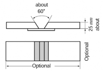
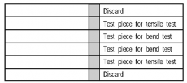
Fig 3 Dimensions and Shape of Test Coupon Fig 4 Test Assembly
(C) Test
Each two test pieces are to be prepared for tension test and bending test respectively as
shown in Fig 4 from the test coupon described in Fig 3.
(a) Tensile test
Tensile test is to be carried out with the welded metal at the center part of the gauge
![]()
length. The value obtained is not to be less than the specified minimum value of the base metal. (Test piece dimension = 14 mm × 70 mm)
(b)
Bending test
Place the welded metal on the center part of test piece, bending to l80° with the inside radius of 25 mm, and confirm that no defects have appeared in the welded part and heat affecting part.
(Test piece dimension = 25 mm × 19 mm × any given length) ![]()
![]()
62 Guidance Relating to the Rules for the Classification of Steel Ships 2015
![]()